One Roof site visit: field companion
High Street, Princes Town · Lot RP1 · printed from the drawing set of
2026-04-11 and our 3D model · prepared 2026-07-30
The one rule. A printed dimension on the drawing beats anyone's tape measure,
including yours. You are not there to re-measure the building. You are there to settle
the six things the drawings genuinely do not answer, and to know which number already
settles the rest. When a figure you are told contradicts a printed label, the label
wins until someone shows you a newer drawing.
1The trip, in this order
Your freshest attention goes to the thing that cannot be recovered later.
Tick as you go.
The building tapers toward the rear, and our model has it right.
94'-6" is the width at the STREET only. The lot is a triangle and the building
follows it, narrowing to an 18'-1" tip where the two washrooms and the lunch room
sit. Settled off the printed dimension chains, and the model matches to within
a quarter inch. So do not spend your best attention here.
Stop 1. The rear elevation, now for a different reason
The taper is settled, so this is no longer the question of the trip. It is still worth two
minutes, because a photo of the real rear is the only thing that can catch a
difference between the drawings and what was actually built. The drawings are a claim;
the building is the fact.
Stop 2. The three retaining walls
The drawings label them "Retaining Wall to Engineer Specs." and give no dimensions
at all. The model has their plan position from the ink and is guessing everything
vertical. It assumes about 11 ft retained. Confirm or correct that number,
it drives the whole site.
Stop 3. The driveway-to-wall joint
The sheets print twice that the driveway around the building is a structural slab bearing
on top of the retaining wall. The model builds it that way at +11.
Stop 4. The quick ones
Do not spend time on these. The lot edges (141'-3" / 17'-2" / 115'-4"), the
lower-ground plate (78'-4" x 77'-2"), the cantilever extents and the wall thicknesses are all
settled from the drawings and already ruled by you. Re-measuring them burns the trip.
2The 9 sheets: print order, what to check, known errors
Print in this order. Each sheet shows our model's equivalent view, so you can
hold the paper against the render and against the building.
Printing: this page is Letter and prints as-is. The architect's own
sheets are worth A3 if you have it, but Letter works. The architect's sheets are worth A3 if
you have it, because their dimension text is small and they were drawn at 1/16" and
3/32" scale, but Letter still works. Do not scale off any print, ever: a
print shrinks by a percent or two, and printed labels are the only scale-free truth.
Sheet 1 of 9 · A2 SITE PLAN
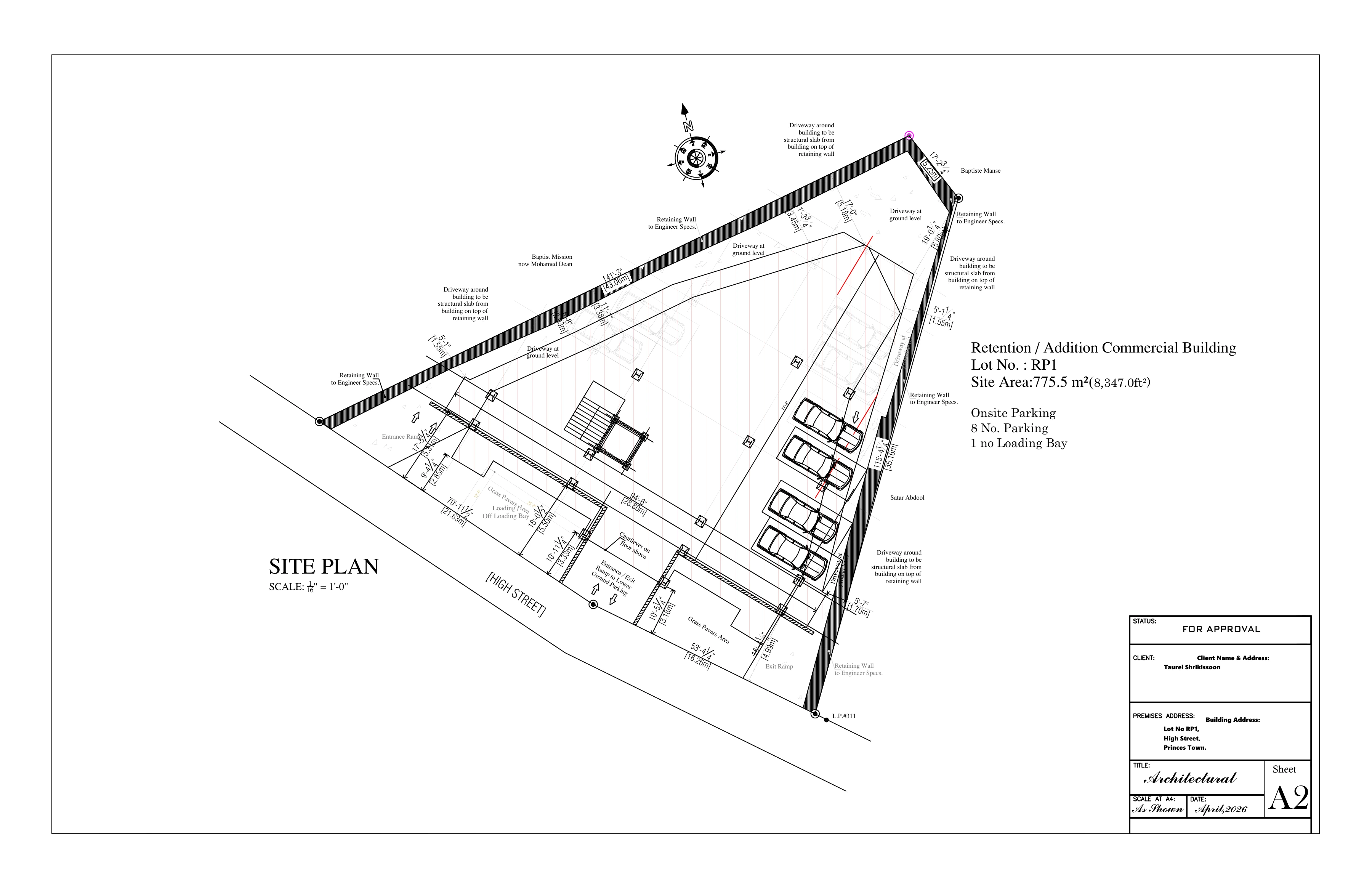 THE DRAWING · A2 SITE PLAN as submitted
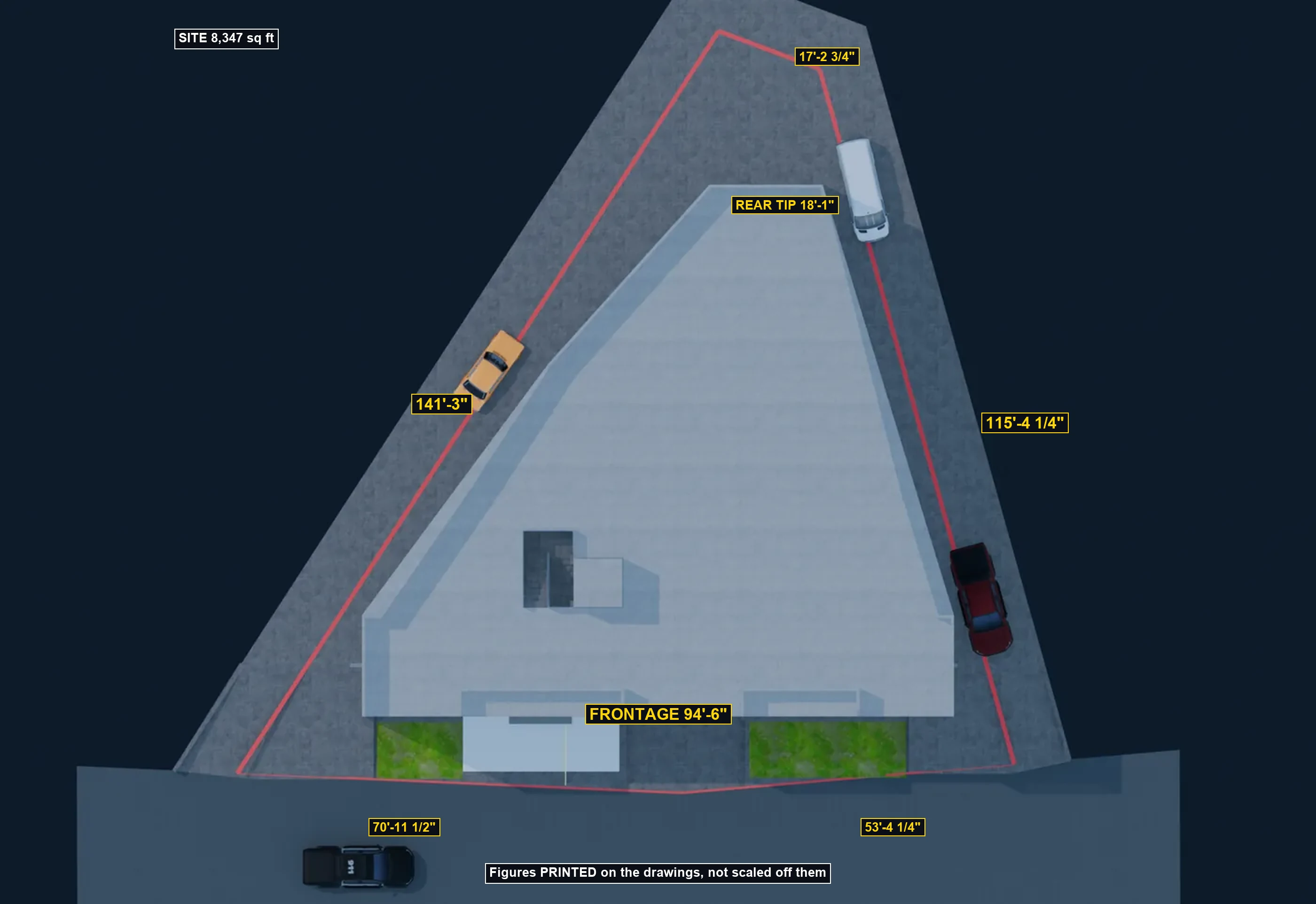 OUR MODEL · top down
What this sheet is: the lot, street, ramps, boundary walls and apron at
1/16"=1'-0". Site area printed 775.5 m2 (8,347 ft2).
Sheet 2 of 9 · A3 LOWER GROUND (parking)
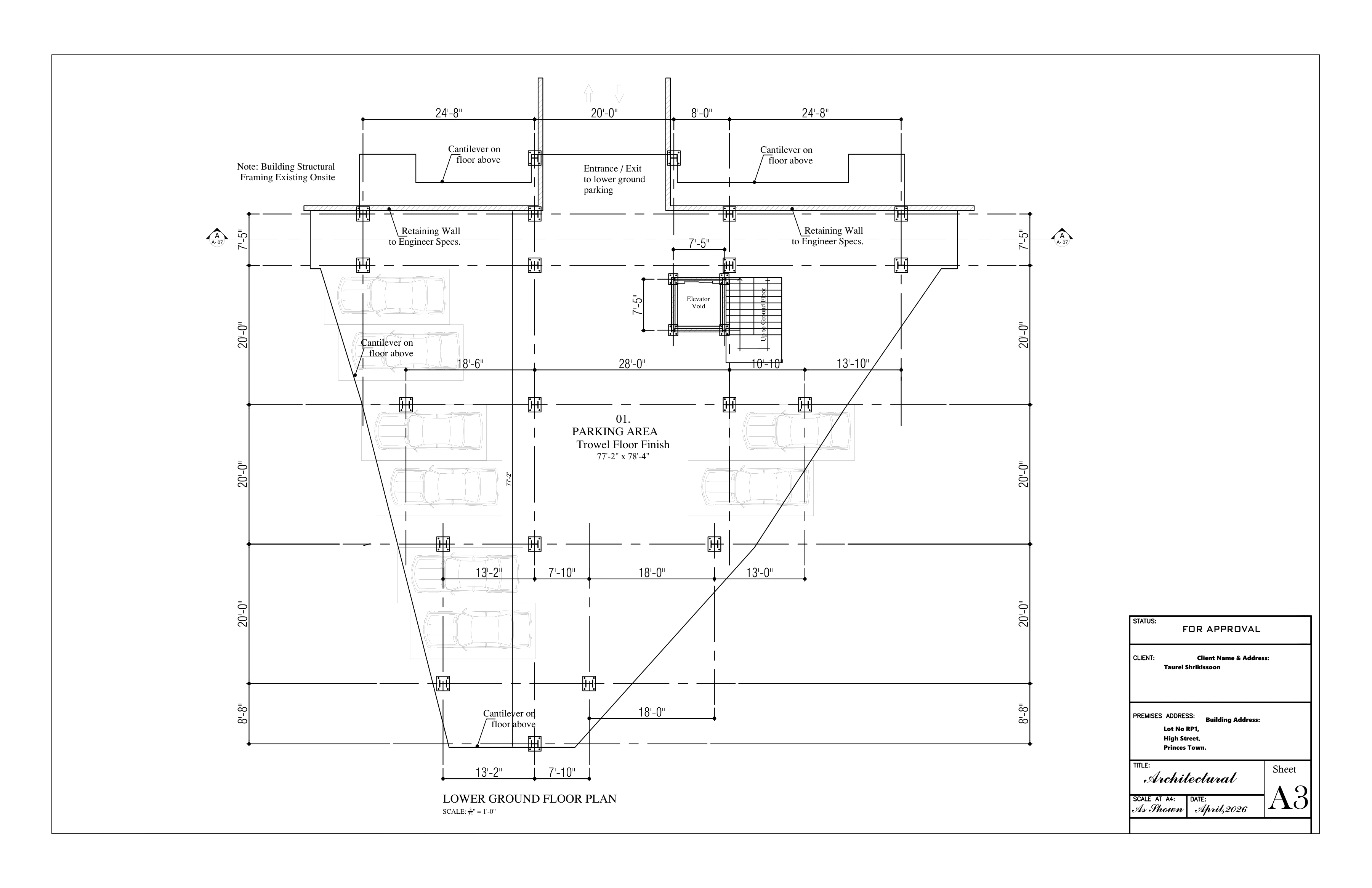 THE DRAWING · A3 as submitted
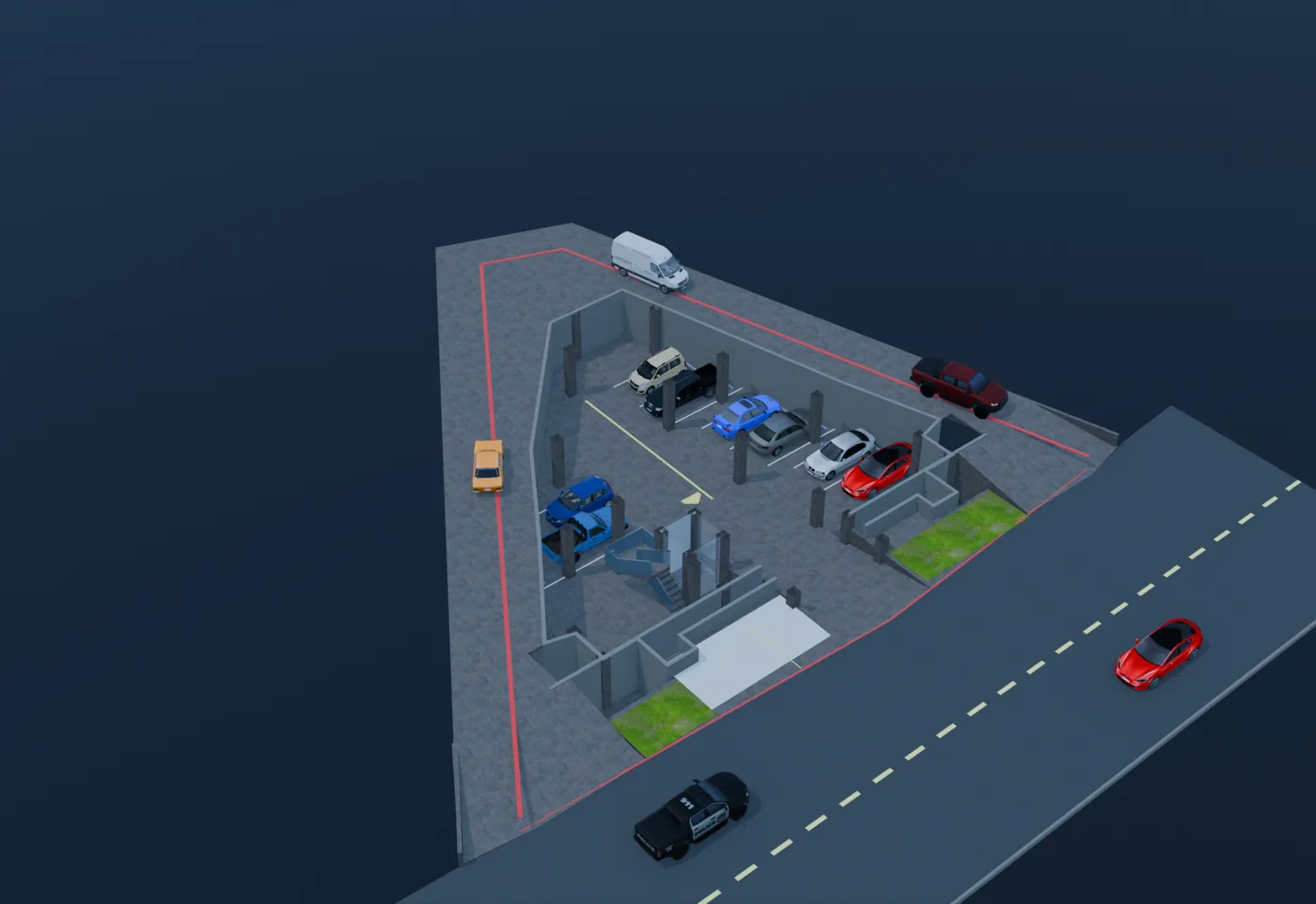 OUR MODEL · parking level
Sheet 3 of 9 · A4 GROUND FLOOR (retail)
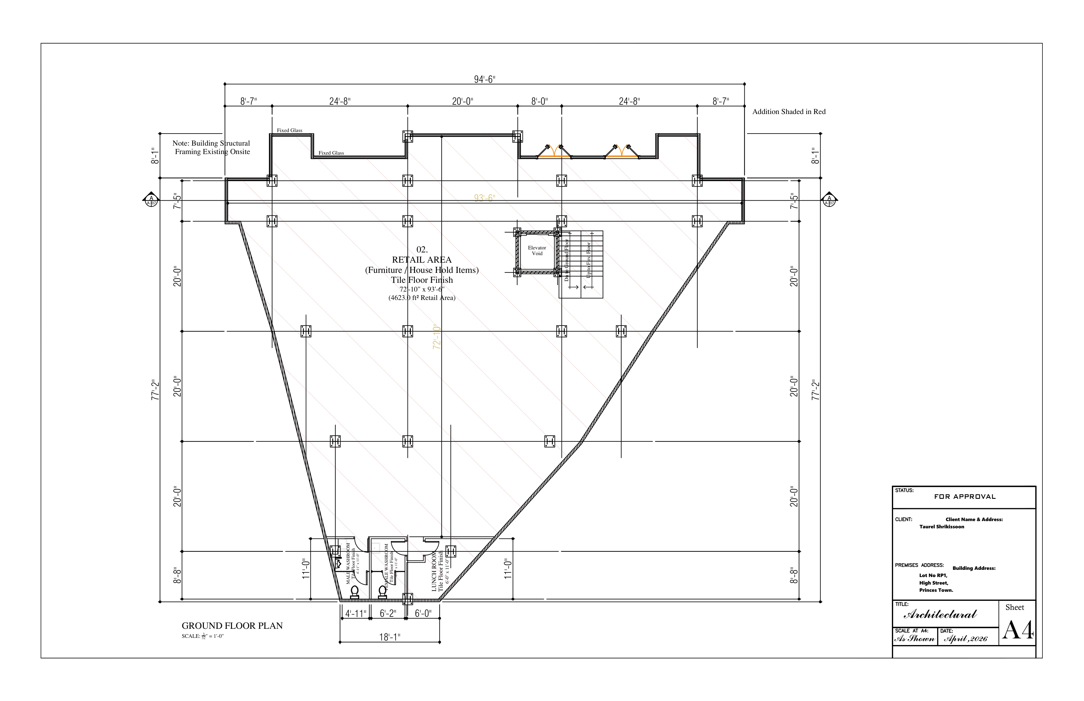 THE DRAWING · A4 as submitted
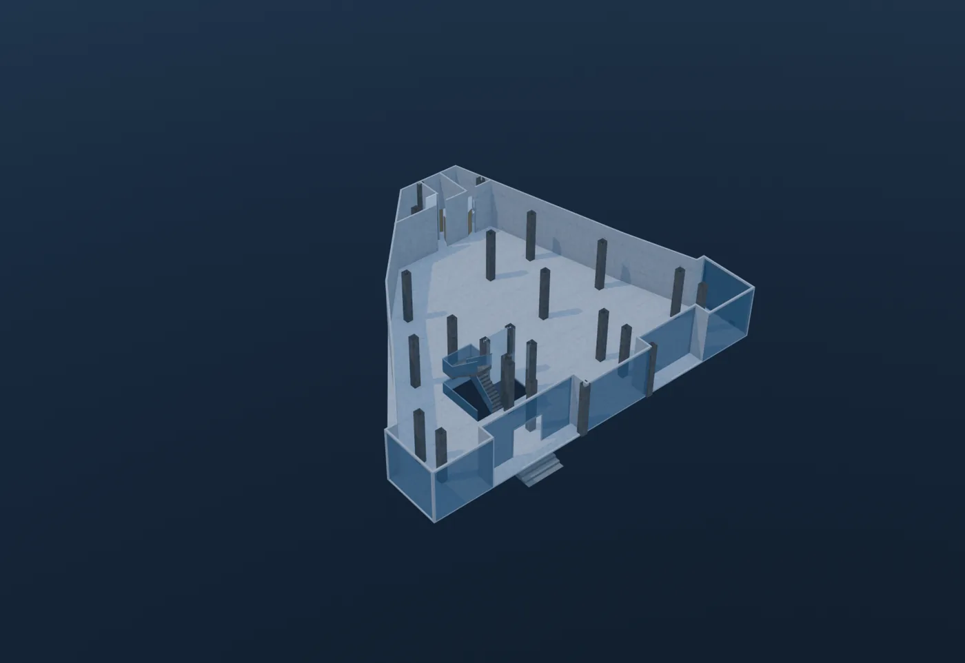 OUR MODEL · ground floor
Sheet 4 of 9 · A5 FIRST FLOOR
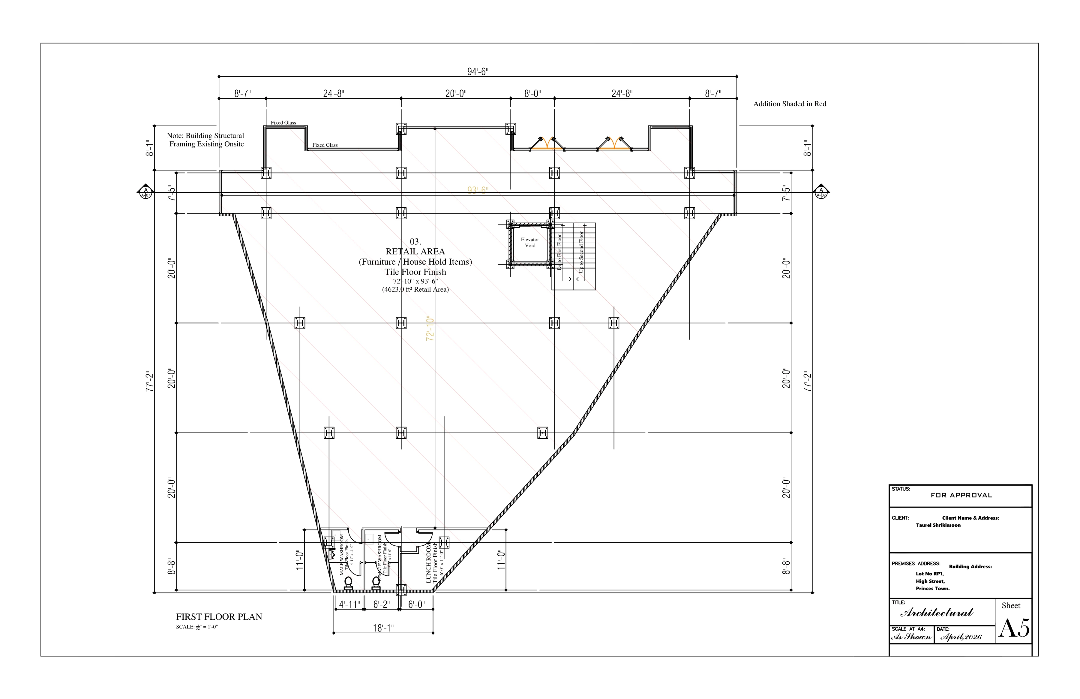 THE DRAWING · A5 as submitted
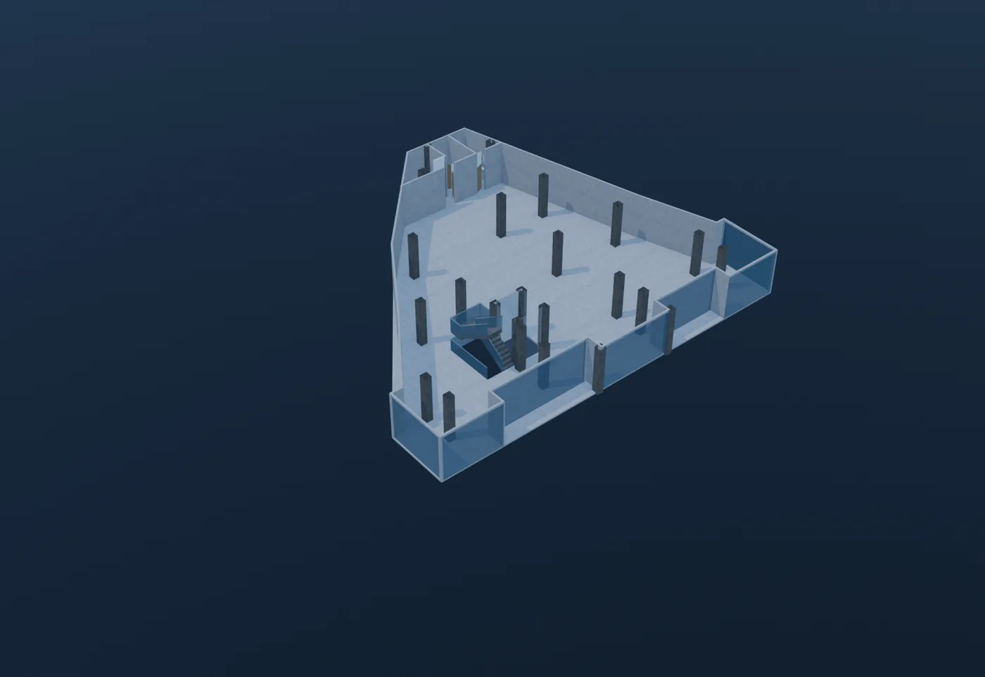 OUR MODEL · first floor
Sheet 5 of 9 · A6 SECOND FLOOR
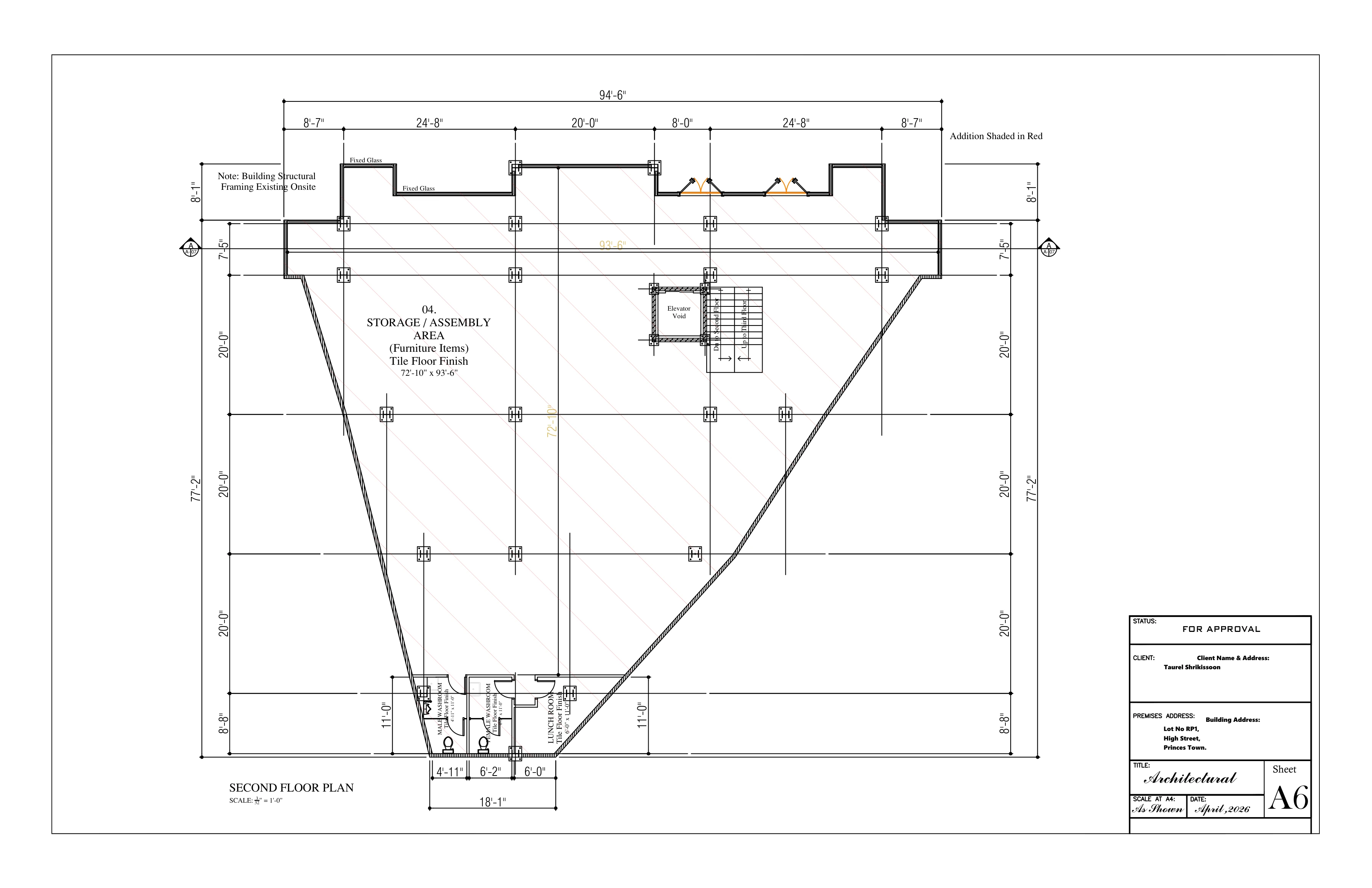 THE DRAWING · A6 as submitted
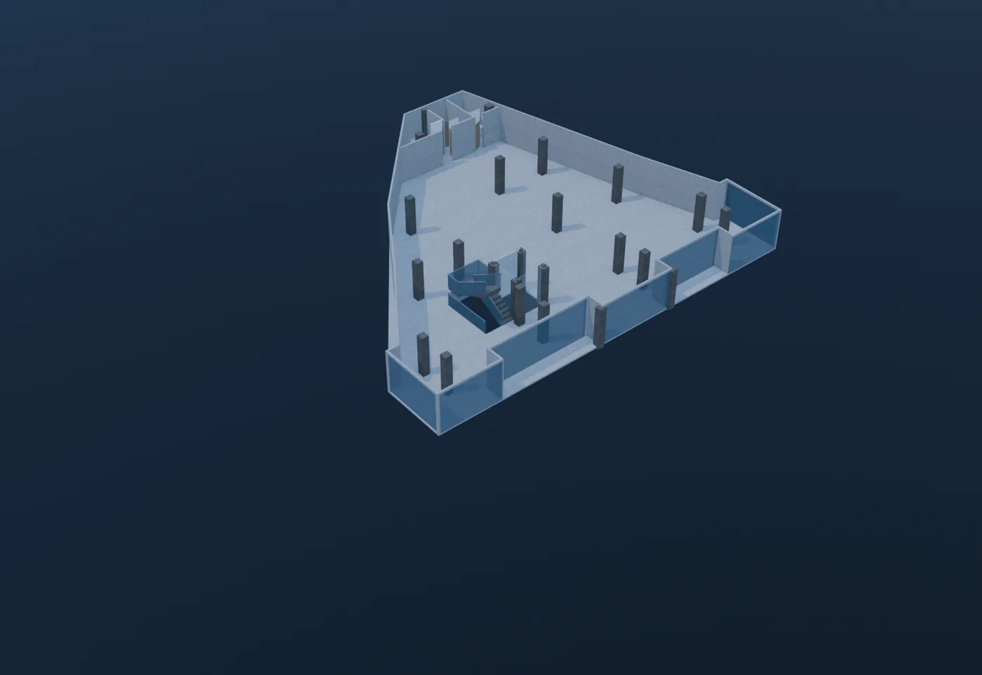 OUR MODEL · second floor
Sheet 6 of 9 · A7 OPEN CONCRETE ROOF
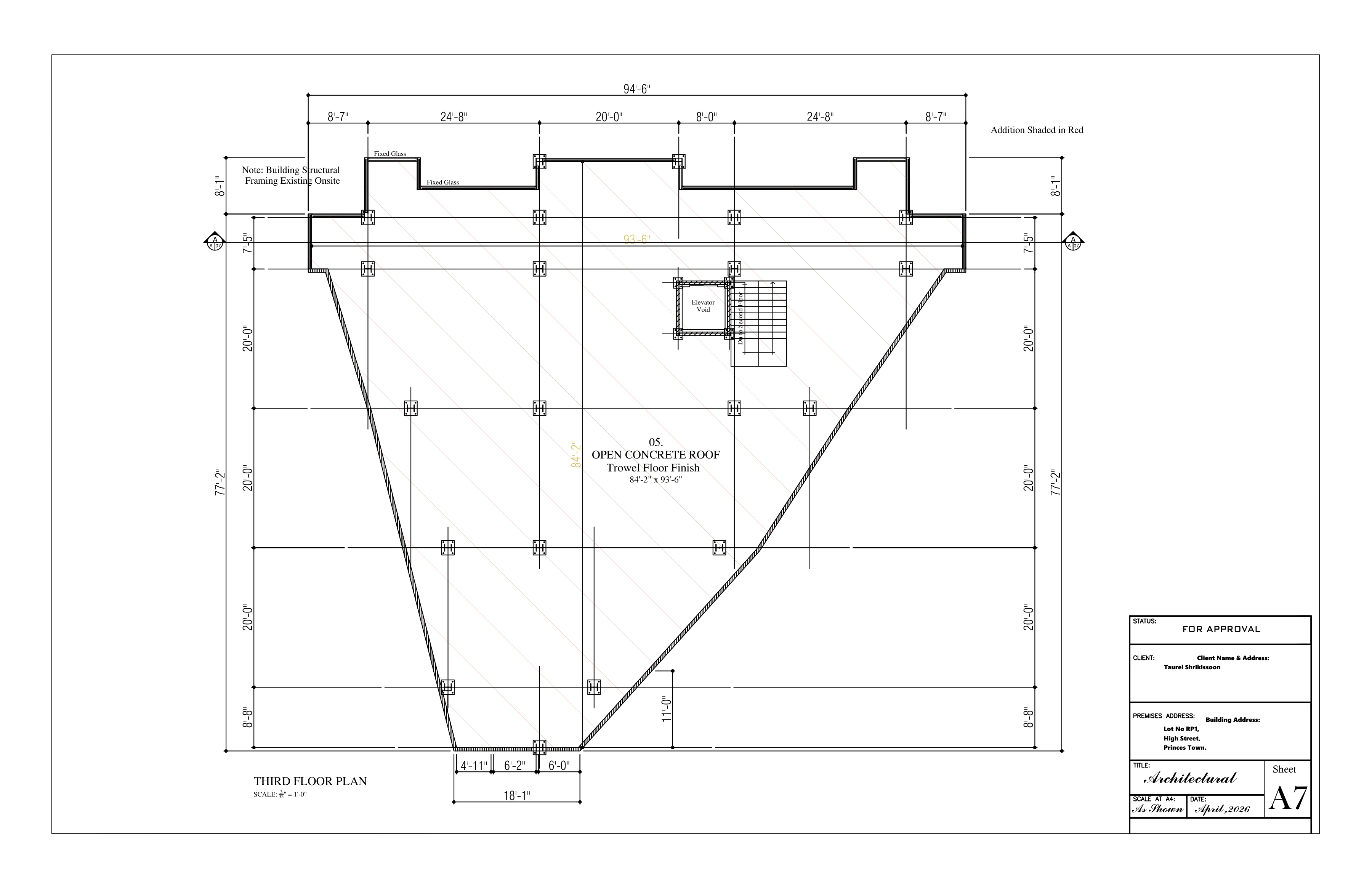 THE DRAWING · A7 as submitted
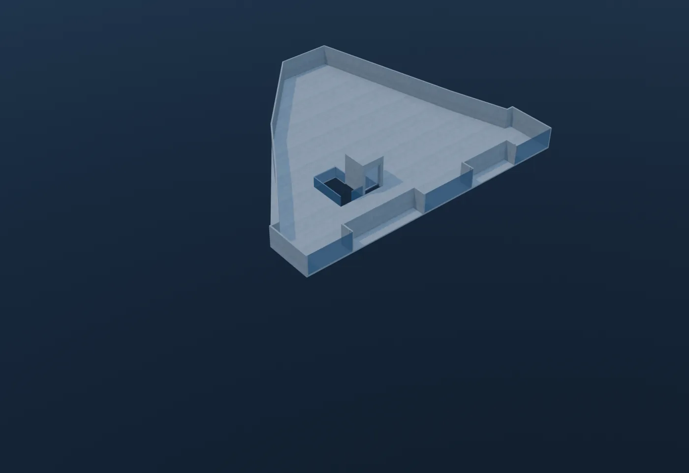 OUR MODEL · roof deck
Sheets 7 to 9 of 9 · A8/A9 ELEVATIONS + SECTION A-A
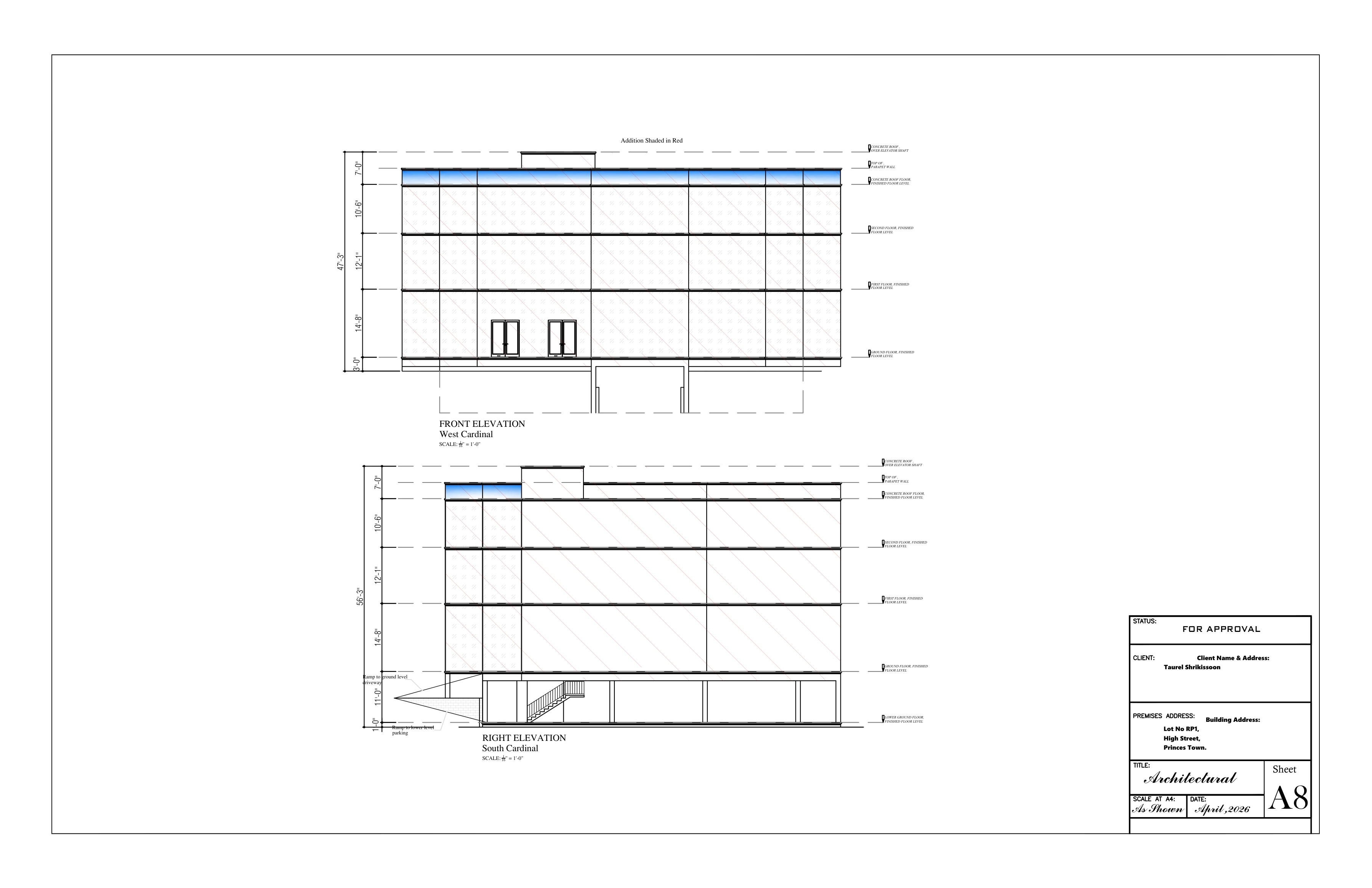 THE DRAWING · FRONT elevation as submitted
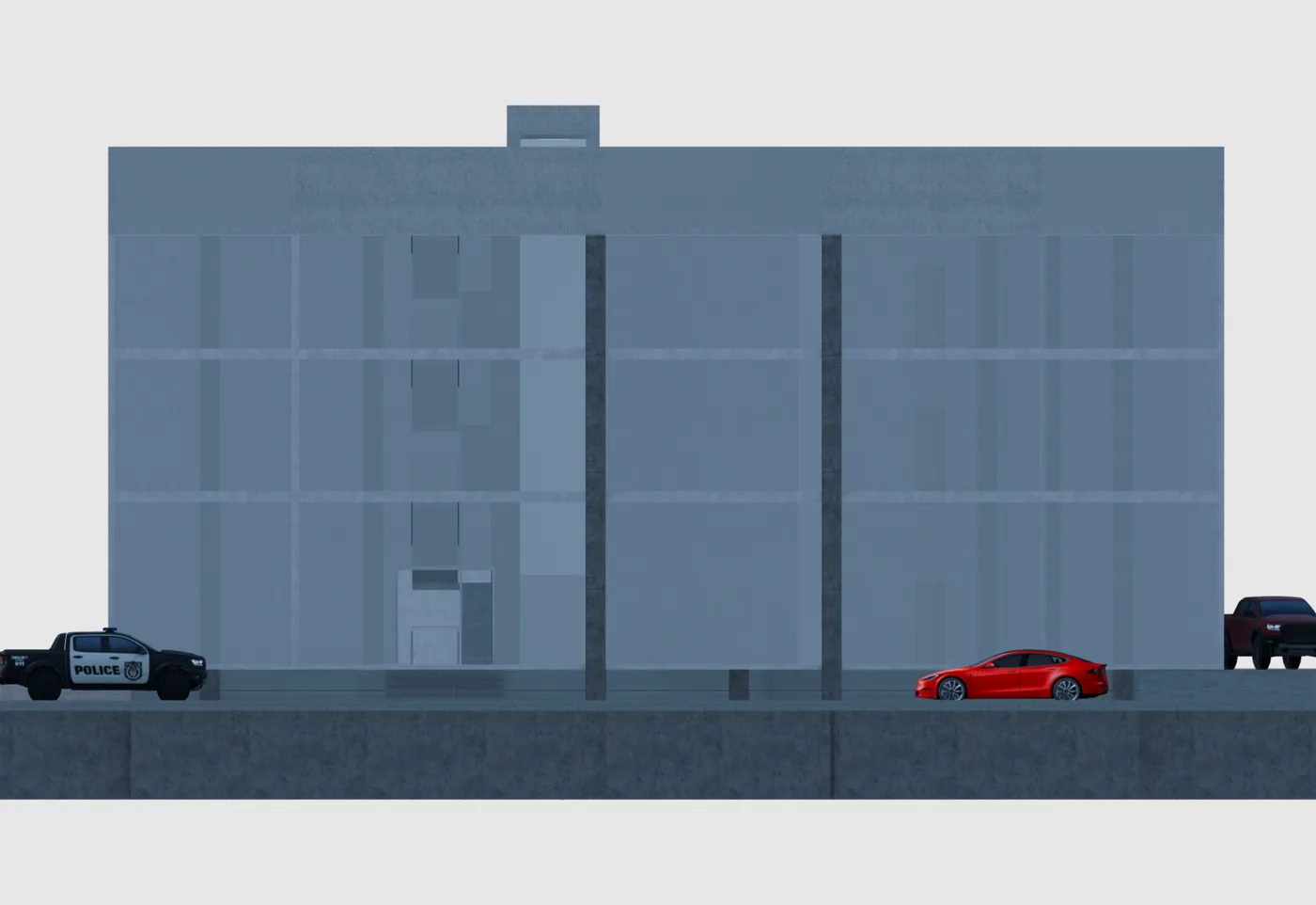 OUR MODEL · front
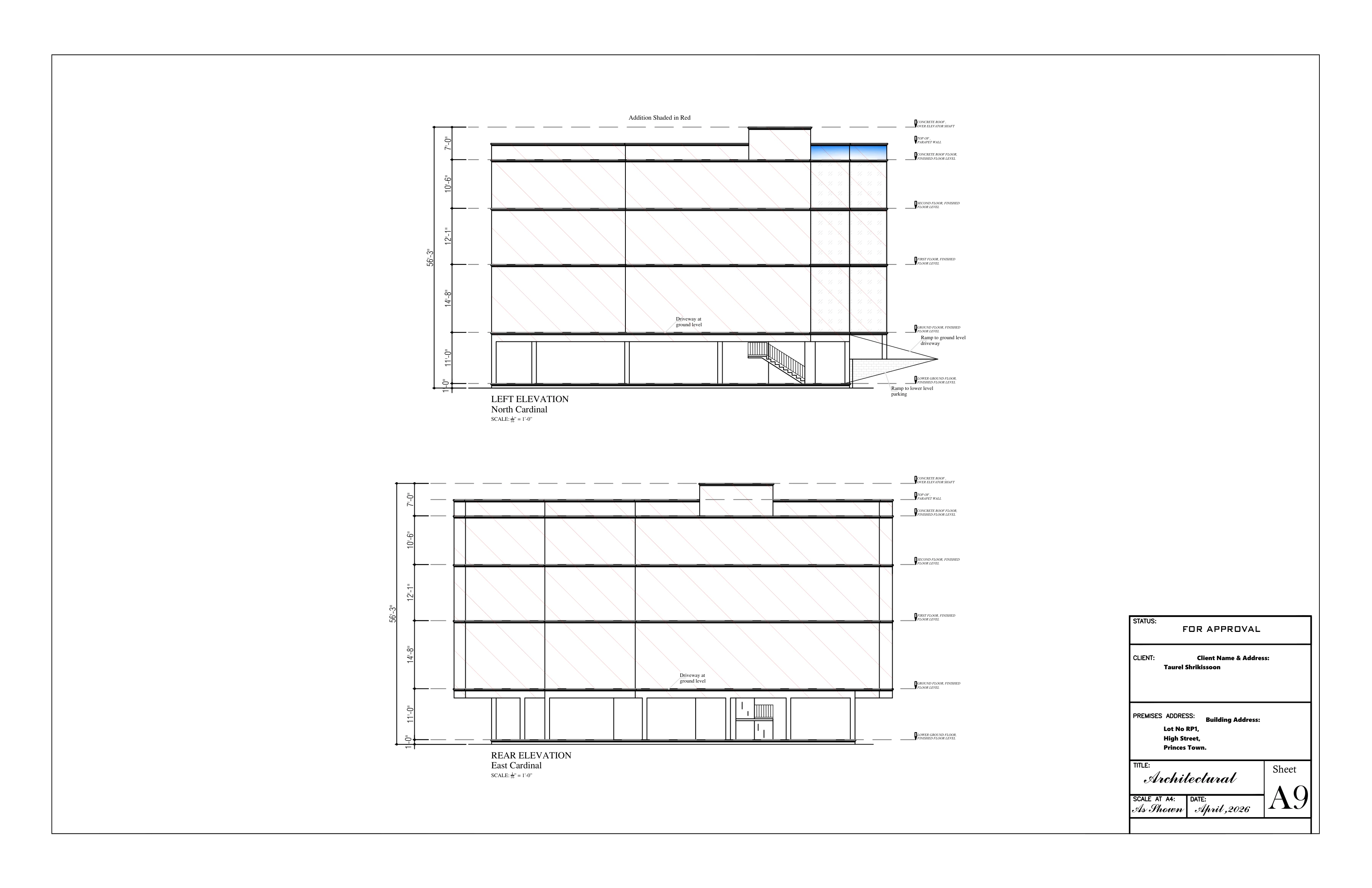 THE DRAWING · REAR elevation as submitted
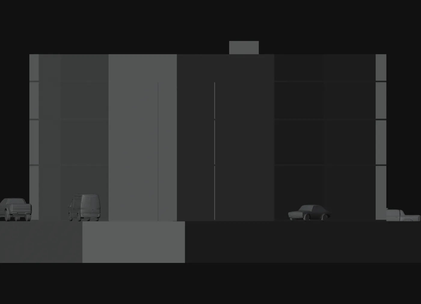 OUR MODEL · rear
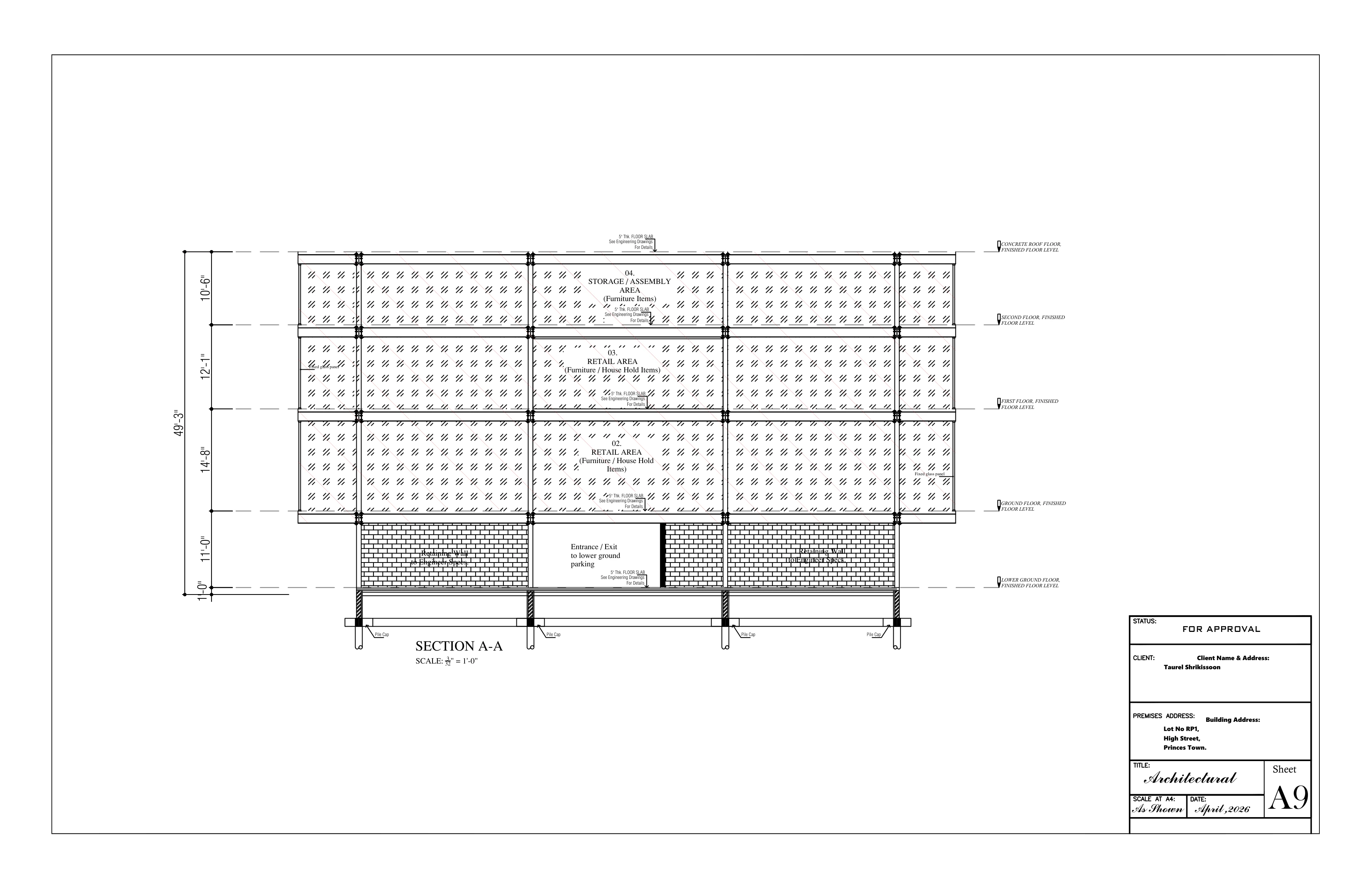 THE DRAWING · SECTION A-A as submitted
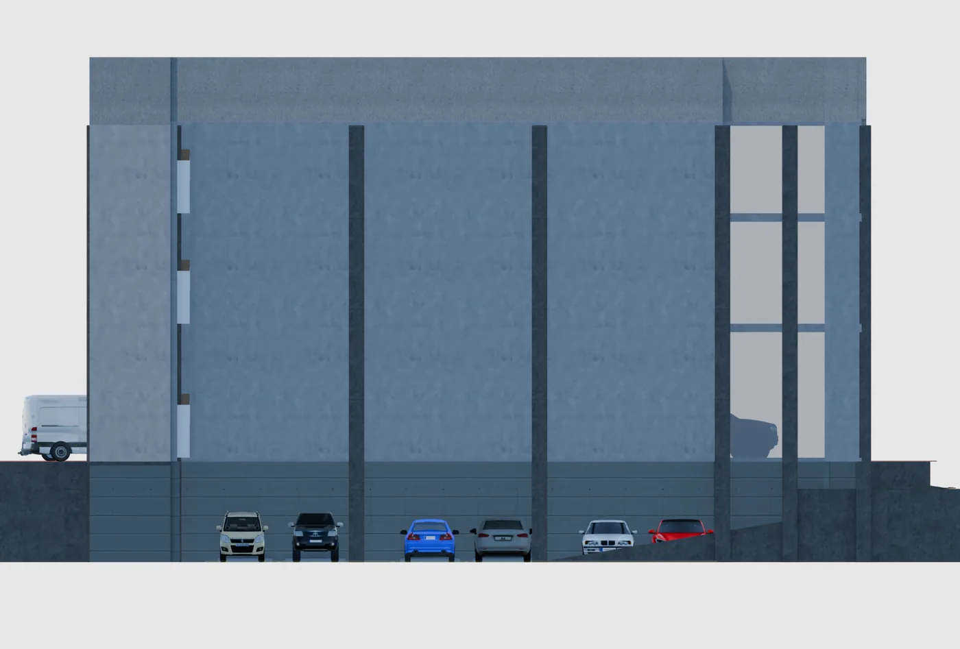 OUR MODEL · cut through
The pattern across the whole set, and it is the most useful thing on this page.
Three floor plans are identical copies, doors and washroom chains and glass labels appear on
sheets where those things do not exist, one page contradicts itself in its own caption, and a
typo survived to submission. Treat any single unchecked detail on these drawings as a
claim rather than a fact, and ask which revision is on site today.
3Eight numbers nobody can bluff you on
Datum is Lower Ground FFL = 0'-0". Everything is measured from that floor, and
every number here is a printed dimension.
Plate: 94'-0" x 84'-8" per floor, 94'-6" frontage.
Every slab is 5 inches, printed at every level including the roof.
The one thing above the parapet, and it is a good question to ask. The lift
and stair over-run, labelled "CONCRETE ROOF OVER ELEVATOR SHAFT", is drawn as an
undimensioned box. No height for it is printed on any of the nine sheets, so
there is no figure to quote. Ask: "The over-run is not dimensioned on the elevations.
What height is it being built to?" If a number is not printed, nobody should be stating
it with confidence, including you.
Three things about THIS building that stop you being misled
1. It is not a simple stack of equal boxes. High Street sits 8'-0" above
the parking floor and 3'-0" below the retail floor. From the front it reads as one storey;
from the rear it is three, because grade drops toward Princess Street and the lower ground is
fully exposed there. Front elevation measures 47'-3", the side measures 56'-3", and that
9'-0" difference is the buried depth, not an error.
2. The parking deck is smaller than the building above it. It starts
about 15'-6" back from the front grid line and is trapezoidal, not rectangular. The upper
floors cantilever out over it along the 94'-6" frontage. Internal parking area is
77'-2" x 78'-4", about 6,045 sq ft, measured from the retaining wall inward.
3. The drawings contradict themselves in places and we did not fix it.
One example: rooms dimensioned 17'-1" against an 18'-1" tail. Do not let anyone quietly
resolve one of those in conversation. Ask which drawing governs and get it in writing.
4Four sanity checks
Each one is arithmetic you can do standing up.
1. The level table must close
Add the rises: 11'-0" + 14'-8" + 12'-1" + 10'-6" = 48'-3", exactly the
printed roof FFL. If someone gives you storey heights that do not add up to the total, one of
the numbers is wrong. This is the fastest lie-detector on site.
2. Concrete for a slab
Area in square feet divided by 65 is cubic yards at 5 inches thick. Our
floor plate is 7,959 sq ft, so about 123 cubic yards per floor slab, or about
135 ordered once you add the standard 10 percent. If you are quoted 40
or 400 for one of these slabs, stop and ask.
3. Is a corner square
Measure 3 along one wall, 4 along the other. The diagonal must be 5. Any
units, any multiple (6-8-10, 9-12-15). If the diagonal is long, the corner is open past 90
degrees; short, and it is closed.
4. Is a ramp usable
Rise divided by run is the gradient. Our front ramp drops 8'-0" to the
parking. Drawn at 16.8 percent, that needs 47.6 ft of run; at the 20 percent
ceiling it needs 40 ft. A ramp much shorter than 40 ft for that drop is too
steep for a car.
5Retaining walls: the two-minute check
You have three, they are undimensioned, and this is the highest-consequence
thing you can look at. Two minutes each.
Inadequate drainage is the single most common cause of retaining wall failure
globally. Water-saturated soil exerts roughly 40 to 60 percent more total lateral
pressure than the same soil drained.
- Find the weep holes. Drainage outlets through the base. Guidance
puts them at maximum 1.5 m centres, 150 to 300 mm above the base, minimum 75 mm diameter.
No weep holes at all is the thing to notice and report.
Dry weep holes after rain suggests drainage is clogged and pressure is building.
Soil coming OUT of a weep hole means the backfill is eroding internally, which
creates voids behind the wall.
- Sight along the wall face for lean or bulge. Any measurable lean
beyond 1:100, which is 10 mm per metre of height, warrants urgent assessment. On an 11 ft
wall that is roughly 34 mm, visible against a plumb line or a level app.
- Look for horizontal cracking across the stem, especially at
mid-height. That indicates bending stress past the wall's reinforced capacity. Vertical
cracking is more commonly settlement.
- White chalky deposits (efflorescence) mean water is moving through
the wall.
- Look at the ground on both sides. Depressions or small sinkholes
behind the wall mean soil is being carried away. Heave or cracking in front of the
toe can point to bearing failure.
If you see clear lean, bulging, or a wide horizontal crack: keep back from it and do
not climb on or near it. A wall under sustained pressure can hold its deformed shape
for a long time and then fail suddenly.
6Cracks, with actual numbers
Severity is a function of width. Carry a gauge card and write the number down.
"A crack" is not data. "0.5 mm, diagonal, east column, 1.2 m above floor" is.
Under BS 8110, widths over 0.3 mm are generally significant. Non-structural
cracks from shrinkage typically measure under 0.2 mm and stay static; cracks that are
progressive, diagonal, or wider than 0.4 mm are frequently symptomatic of
serious issues.
The pattern matters as much as the width
Spalling, honeycombing, and what cover means
"Cover" is the depth of concrete between the outer face and the steel. It
is the only thing protecting the steel from water and air. When water reaches the steel it
rusts, and rust occupies several times the original volume, generating pressure put at over
20 MPa, which forces the surface to flake off. That is spalling. Rust staining
usually appears before the spalling does, which makes it the early warning.
The threshold worth remembering: spalling affecting more than 25 percent
of a column's cross-sectional area, or occurring at a beam-column junction, is classified as
a high-priority structural emergency. Beam-column junctions are the single most important
places in a frame.
Honeycombing is patches where the concrete looks like coarse gravel with
voids, usually on vertical rather than horizontal surfaces. It can occasionally extend
completely through a member, which makes that member structurally unsound. Photograph it,
note where, note how deep it looks.
The load path, and what each part does
A building is a machine for getting weight into the ground. Weight lands on a floor, the
floor hands it to a beam, the beam to a column, the column to a foundation, the foundation to
soil. That chain is the load path. Looking at any part, ask: what holds this
up, and where does that load go next. If you cannot answer, photograph it.
Yours is a reinforced concrete frame: columns and beams do the structural
work, most walls fill in between. Concrete is excellent in compression and nearly useless in
tension, so steel goes exactly where the concrete would be pulled apart.
The soft-storey shape, which your building has. If one level has far
fewer walls than the levels above, that level is much more flexible than the rest. Your lower
ground is exactly this: an open parking level under solid floors. It is a recognised
vulnerability pattern in earthquakes. This is a question for your engineer, not
something you can assess by eye, but it is the right question to ask.
7What to ask
Each one arises from something actually printed on the set.
The highest-value question on this trip is not about dimensions at all.
"Who is the structural engineer of record, which code did they design to, and can I see
the stamped drawings?" There is no approved national building code in Trinidad and
Tobago, so which code the design was done to is a choice your engineer made. In a seismic
region the detailing at beam-column joints is where a frame survives or does not, and that is
engineering you cannot see in a photograph.
- "The slab note says 5 inches, see engineering drawings for details. Can I
have the engineering drawings?" The architectural set carries the thickness but not
the reinforcement. If nobody can produce the structural set, that is the finding.
- "The driveway around the building is noted as a structural slab. What is
it bearing on?" The note says it bears on the boundary walls. Worth hearing them say
the same thing.
- "What gradient did the ramps actually get built to?" Drawn at 16.8
percent. Anything over 20 percent is a problem for customer cars, and this is retail.
- "The whole front is glazed across three storeys. What is the glass spec
and who signed off the wind load?" The most expensive and most exposed thing on the
drawings.
- "Which drawing revision is on site today?" Everything here is only
true of the set we traced. A newer revision beats all of it, and knowing there is one is
worth the trip.
8Kit, and how to measure so it is usable
The one discipline that makes the photos usable. For every number, say out
loud in a voice note: where you are standing, and what you are measuring from and
to. "Wall height, north corner, driveway surface to top of wall" beats "eleven feet"
enormously. The failure in this model has never been bad numbers. It has been not knowing
what a line referred to.
The other six measuring laws
Name both faces. Inside-face-to-inside-face is a different number from
outside-to-outside, and on a wall of unknown thickness those differ by a foot or more.
One long measurement beats many short ones. Measure five bays and add
them and you accumulate five errors. Measure the whole run once, then the parts, then check
the parts sum to the whole. When they disagree you have found something real.
Wide before close, and never close alone. A close-up with no context
cannot be placed later. Every close-up gets a wide shot from the same spot first, with
something of known size in frame.
Square on, or say you could not. An angled photo of a wall cannot be
measured off later. If you cannot get square, take it anyway and say so.
Record what you could NOT do. An honest gap is workable. A silent gap
looks like a measurement nobody bothered with, and someone downstream will assume the drawing
was right.
Consistent light. Do the whole exterior in one pass rather than half now
and half at dusk, so subtle deformations are not overlooked.
What a builder means when he says it
The tools you will see, and what they are actually good for
The catch worth knowing: that 2 mm is a laboratory figure at 95 percent
confidence. In poor conditions it degrades by about 0.15 mm per metre beyond 5 m, and long
shots drift further. So a 100 ft reading is not as tight as a 10 ft one. Ask what they aimed
at: a dark, shiny or angled surface reads worse than a matt wall.
If you want to go further than looking
The standard next-step tests, so you know what to ask for rather than being sold
something. All non-destructive unless noted.
Chloride profiling matters in a coastal humid climate specifically,
because chloride is what breaks down the steel's protective layer.
9The honest limits of this page
- Our numbers are from the drawing set, not the built structure. If the
site differs from the drawings, the site is the fact and the drawings are the claim.
Measuring that gap is the single most valuable thing you can bring back.
- Nobody here has been on this site. Everything above is drawings plus
sourced general practice.
- The 3-storey model is built from the same drawings, so it agrees with
this page by construction. It is not independent confirmation.
- What I am not: a structural engineer, and neither are you. This is aimed
at gathering evidence and flagging anything that looks wrong so a qualified engineer can
look at it. "Photograph the diagonal crack" is your job. "The beam is failing in shear" is
not.
- No seismic zone classification, design ground acceleration, or concrete detailing
clauses for T&T are quoted here, because the official evaluation document is a
scan whose tables are not machine-readable and a plausible-sounding number is not a real
one. Those come from the engineer of record or from TTBS directly.